Television is certainly one of the most influential forces
of our time. Through the device called a television set
or TV, you are able to receive news, sports,
entertainment, information and commercials. The average
American spends between two and five hours a day glued to "the
tube"!
Have you ever wondered about the
technology that makes television possible? How is it that
dozens or hundreds of channels of full-motion video arrive at
your house, in many cases for free? How does your television
decode the signals to produce the picture? How will the new
digital television signals change things? If you have ever
wondered about your television (or, for that matter, about
your computer monitor), then read on! In this edition ofHowStuffWorks,
we'll answer all of these questions and more!
Two Amazing Things About the Brain
Let's start at
the beginning with a quick note about your brain. There are two amazing things about your brain that
make television possible. By understanding these two facts,
you gain a good bit of insight into why televisions are
designed the way they are.
Start by watching the following video clip. Simply click on
the picture and at the dialog that appears select the "Open"
option:
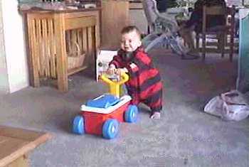
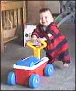
This is a standard piece of home video
showing a happy baby playing with a toy. It is encoded as an
MPEG
file so that you can view it on your computer, and it embodies
the two principles that make TV possible.
The first principle is this: If you divide a still image
into a collection of small colored dots, your brain will
reassemble the dots into a meaningful image. This is no
small feat, as any researcher who has tried to program a
computer to understand images will tell you. The only way we
can see that this is actually happening is to blow the dots up
so big that our brains can no longer assemble them, like this:
Most people, sitting right up close to
their computer screens, cannot tell what this is a picture of -- the dots
are too big for your brain to handle. If you stand 10 to 15
feet away from your monitor, however, your brain will be able
to assemble the dots in the image and you will clearly see
that it is the baby's face. By standing at a distance, the
dots become small enough for your brain to integrate them into
a recognizable image.
Both televisions and computer screens (as well as newspaper
and magazine photos) rely on this fusion-of-small-colored-dots
capability in the human brain to chop pictures up into
thousands of individual elements. On a TV or computer screen,
the dots are called pixels. The resolution of your
computer's screen might be 800x600 pixels, or maybe 1024x768
pixels.
The human brain's second amazing feature relating to
television is this: If you divide a moving scene into a
sequence of still pictures and show the still images in rapid
succession, the brain will reassemble the still images into a
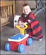
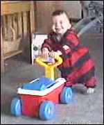
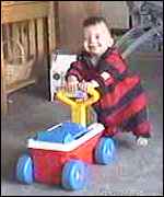
single moving scene. Take, for example, these four frames
from the example video:
Each one of these images is slightly different from the
next. If you look carefully at the baby's left foot (the foot
that is visible), you will see that it is rising in these four
frames. The toy also moves forward very slightly. By putting
together 15 or more subtly different frames per second, the
brain integrates them into a moving scene. Fifteen per second
is about the minimum possible -- any fewer than that and it
looks jerky.
When you download and watch the MPEG file offered at the
beginning of this section, you see both of these processes at
work simultaneously. Your brain is fusing the dots of each
image together to form still images and then fusing the
separate still images together into a moving scene. Without
these two capabilities, TV as we know it would not be
possible.
The Cathode Ray Tube
Almost all TVs in use
today rely on a device known as the cathode ray tube,
or CRT, to display
their images. LCDs and plasma displays are sometimes seen, but
they are still rare when compared to CRTs. It is even possible
to make a television screen out of thousands of ordinary
60-watt light bulbs! You may have seen something like this at an outdoor
event like a football game. Let's start with the CRT, however,
because CRTs are the most common way of displaying images
today.
The terms anode and cathode are used in electronics as
synonyms for positive and negative terminals. For example, you
could refer to the positive terminal of a battery
as the anode and the negative terminal as the cathode.
|
PhosphorA
phosphor is any material that,
when exposed to radiation, emits visible light. The radiation might be ultraviolet light or a
beam of electrons. Any fluorescent color is really a
phosphor -- fluorescent colors absorb invisible
ultraviolet light and emit visible light at a
characteristic color.
In a CRT, phosphor coats the inside of the screen.
When the electron beam strikes the phosphor, it makes
the screen glow. In a black-and-white screen, there is
one phosphor that glows white when struck. In a color
screen, there are three phosphors arranged as dots or
stripes that emit red, green and blue light. There are
also three electron beams to illuminate the three
different colors together.
There are thousands of different phosphors that have
been formulated. They are characterized by their
emission color and the length of time emission lasts
after they are excited.
|
In a
cathode ray tube, the "cathode" is a heated filament (not
unlike the filament in a normal light bulb). The heated filament is in a
vacuum created inside a glass "tube." The "ray" is a stream of
electrons that naturally pour off a heated cathode into the
vacuum.
Electrons are negative. The anode is positive, so it
attracts the electrons pouring off the cathode. In a TV's
cathode ray tube, the stream of electrons is focused by a
focusing anode into a tight beam and then accelerated by an
accelerating anode. This tight, high-speed beam of electrons
flies through the vacuum in the tube and hits the flat screen
at the other end of the tube. This screen is coated with
phosphor, which glows when struck by the beam.
As you can see in the above drawing, there's not a whole
lot to a basic cathode ray tube. There is a cathode and a pair
(or more) of anodes. There is the phosphor-coated screen.
There is a conductive coating inside the tube to soak up the
electrons that pile up at the screen-end of the tube. However,
in this diagram you can see no way to "steer" the beam -- the
beam will always land in a tiny dot right in the center of the
screen.
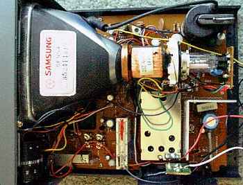
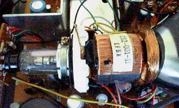
That's why, if you look inside any TV set, you will find
that the tube is wrapped in coils of wires. The following
pictures give you three different views of a typical set of
steering coils:
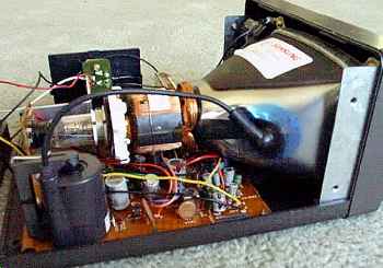
(Note the large black electrode hooked to the
tube near the screen -- it is connected internally to
the conductive
coating.)
|
The steering coils are simply copper
windings (see How Electromagnets Work for details on coils). These coils are
able to create magnetic fields inside the tube, and the
electron beam responds to the fields. One set of coils creates
a magnetic field that moves the electron beam vertically,
while another set moves the beam horizontally. By controlling
the voltages in the coils, you can position the electron beam
at any point on the screen.
The Black-and-White TV Signal
In a
black-and-white TV, the screen is coated with white phosphor
and the electron beam "paints" an image onto the screen by
moving the electron beam across the phosphor a line at a time.
To "paint" the entire screen, electronic circuits inside the
TV use the magnetic coils to move the electron beam in a
"raster scan" pattern across and down the screen. The
beam paints one line across the screen from left to right. It
then quickly flies back to the left side, moves down slightly
and paints another horizontal line, and so on down the screen,
like this:
|
In this figure, the blue lines represent lines that the
electron beam is "painting" on the screen from left to right,
while the red dashed lines represent the beam flying back to
the left. When the beam reaches the right side of the bottom
line, it has to move back to the upper left corner of the
screen, as represented by the green line in the figure. When
the beam is "painting," it is on, and when it is flying back,
it is off so that it does not leave a trail on the screen. The
term horizontal retrace is used to refer to the beam
moving back to the left at the end of each line, while the
term vertical retrace refers to its movement from
bottom to top.
As the beam paints each line from left to right, the
intensity of the beam is changed to create different shades of
black, gray and white across the screen. Because the lines are
spaced very closely together, your brain integrates them into
a single image. A TV screen normally has about 480 lines
visible from top to bottom.
Standard TVs use an interlacing technique when
painting the screen. In this technique, the screen is painted
60 times per second but only half of the lines are painted per
frame. The beam paints every other line as it moves down the
screen -- for example, every odd-numbered line. Then, the next
time it moves down the screen it paints the even-numbered
lines, alternating back and forth between even-numbered and
odd-numbered lines on each pass. The entire screen, in two
passes, is painted 30 times every second. The alternative to
interlacing is called progressive scanning, which paints every line on the screen 60 times
per second. Most computer monitors use progressive scanning because it significantly
reduces flicker.
Because the electron beam is painting all 525 lines 30
times per second, it paints a total of 15,750 lines per
second. (Some people can actually hear this frequency as a
very high-pitched sound emitted when the television is on.)
When a television station wants to
broadcast a signal to your TV, or when your VCR
wants to display the movie on a video tape on your TV, the
signal needs to mesh with the electronics controlling the beam
so that the TV can accurately paint the picture that the TV
station or VCR sends. The TV station or VCR therefore sends a
well-known signal to the TV that contains three different
parts:
- Intensity information for the beam as it paints
each line
- Horizontal-retrace signals to tell the TV when to
move the beam back at the end of each line
- Vertical-retrace signals 60 times per second to
move the beam from bottom-right to top-left
A signal
that contains all three of these components is called a
composite video signal.
A composite-video input on a VCR
is normally a yellow RCA jack. One line of a typical composite
video signal looks something like this:
The horizontal-retrace signals are 5-microsecond
(abbreviated as "us" in the figure) pulses at zero
volts. Electronics inside the TV can detect these pulses and
use them to trigger the beam's horizontal retrace. The actual
signal for the line is a varying wave between 0.5 volts and
2.0 volts, with 0.5 volts representing black and 2 volts
representing white. This signal drives the intensity circuit
for the electron beam. In a black-and-white TV, this signal
can consume about 3.5 megahertz (MHz) of bandwidth, while in a
color set the limit is about 3.0 MHz.
A vertical-retrace pulse is similar to a horizontal-retrace
pulse but is 400 to 500 microseconds long. The
vertical-retrace pulse is serrated with
horizontal-retrace pulses in order to keep the
horizontal-retrace circuit in the TV synchronized.
Adding Color
A color TV screen differs from
a black-and-white screen in three ways:
- There are three electron beams that move simultaneously
across the screen. They are named the red, green and blue
beams.
- The screen is not coated with a single sheet of phosphor
as in a black-and-white TV. Instead, the screen is coated
with red, green and blue phosphors arranged in dots or
stripes. If you turn on your TV or computer monitor and look
closely at the screen with a magnifying glass, you will be
able to see the dots or stripes.
- On the inside of the tube, very close to the phosphor
coating, there is a thin metal screen called a shadow
mask. This mask is perforated with very small holes that
are aligned with the phosphor dots (or stripes) on the
screen.
The following figure shows how the shadow
mask works:
|
 |
When a color TV needs to create a red dot, it fires the red
beam at the red phosphor. Similarly for green and blue dots.
To create a white dot, red, green and blue beams are fired
simultaneously -- the three colors mix together to create
white. To create a black dot, all three beams are turned off
as they scan past the dot. All other colors on a TV screen are
combinations of red, green and blue.
A color TV signal starts off looking just like a
black-and-white signal. An extra chrominance signal is
added by superimposing a 3.579545 MHz sine wave onto the
standard black-and-white signal. Right after the horizontal
sync pulse, eight cycles of a 3.579545 MHz sine wave are added
as a color burst.
Following these eight cycles, a phase shift in the
chrominance signal indicates the color to display. The
amplitude of the signal determines the saturation. The
following table shows you the relationship between color and
phase:
|
Color |
Phase |
|
Burst |
0 degrees |
|
Yellow |
15 degrees |
|
Red |
75 degrees |
|
Magenta |
135 degrees |
|
Blue |
195 degrees |
|
Cyan |
255 degrees |
|
Green |
315
degrees |
A black-and-white TV filters out and ignores the
chrominance signal. A color TV picks it out of the signal and
decodes it, along with the normal intensity signal, to
determine how to modulate the three color beams.
Getting the Signal to You
Now you are
familiar with a standard composite video signal. Note that we
have not mentioned sound. If your VCR has a yellow
composite-video jack, you've probably noticed that there are
separate sound jacks right next to it. Sound and video are
completely separate in an analog TV.
You are probably familiar with five different ways to get a
signal into your TV set:
- Broadcast programming received through an antenna
- VCR or DVD player that connects to the antenna terminals
- Cable TV arriving in a set-top box that connects to the
antenna terminals
- Large (6 to 12 feet) satellite-dish antenna arriving in
a set-top box that connects to the antenna terminals
- Small (1 to 2 feet) satellite-dish antenna arriving in a
set-top box that connects to the antenna terminals
The first four signals use standard NTSC analog
waveforms as described in the previous sections. As a starting
point, let's look at how normal broadcast signals arrive at
your house.
A typical TV signal as described above requires 4 MHz of
bandwidth. By the time you add in sound, something called a
vestigial sideband and a little buffer space, a TV signal requires 6
MHz of bandwidth. Therefore, the FCC allocated three bands of
frequencies in the radio spectrum, chopped into 6-MHz slices, to accommodate TV
channels:
- 54 to 88 MHz for channels 2 to 6
- 174 to 216 MHz for channels 7 through 13
- 470 to 890 MHz for UHF channels 14 through 83
The composite TV signal described in the previous
sections can be broadcast to your house on any available
channel. The composite video signal is amplitude-modulated
into the appropriate frequency, and then the sound is
frequency-modulated (+/- 25 KHz) as a separate signal, like
this:
To the left of the video carrier is the
vestigial lower sideband (0.75 MHz), and to the right is the
full upper sideband (4 MHz). The sound signal is centered on
5.75 MHz. As an example, a program transmitted on channel 2
has its video carrier at 55.25 MHz and its sound carrier at
59.75 MHz. The tuner in your TV, when tuned to channel 2,
extracts the composite video signal and the sound signal from
the radio waves that transmitted them to the antenna.
VCRs are
essentially their own little TV stations. Almost all VCRs have
a switch on the back that allows you to select channel 3 or 4.
The video tape contains a composite video signal and a separate
sound signal. The VCR has a circuit inside that takes the
video and sound signals off the tape and turns them into a
signal that, to the TV, looks just like the broadcast signal
for channel 3 or 4.
The cable incable
TV contains a large number of channels that are
transmitted on the cable. Your cable provider could simply
modulate the different cable-TV programs onto all of the
normal frequencies and transmit that to your house via the
cable; then, the tuner in your TV would accept the signal and
you would not need a cable box. Unfortunately, that approach
would make theft of cable services very easy, so the signals
are encoded in funny ways. The set-top box is a
decoder. You select the channel on it, it decodes the right
signal and then does the same thing a VCR does to transmit the
signal to the TV on channel 3 or 4.
Large-dish satellite antennas pick off unencoded or encoded signals
being beamed to Earth by satellites.
First, you point the dish to a particular satellite, and then
you select a particular channel it is transmitting. The
set-top box receives the signal, decodes it if necessary and
then sends it to channel 3 or 4.
Small-dish satellite systems are digital. The TV programs are encoded
in MPEG-2
format and transmitted to Earth. The set-top box does a lot of
work to decode MPEG-2, then converts it to a standard analog
TV signal and sends it to your TV on channel 3 or 4.
Digital TV
The latest buzz is digital
TV, also known as DTV or HDTV
(high-definition TV). DTV uses MPEG-2 encoding just like the
satellite systems do, but digital TV allows a variety of new, larger
screen formats. The formats include:
- 480p - 640x480 pixels progressive
- 720p - 1280x720 pixels progressive
- 1080i - 1920x1080 pixels interlaced
- 1080p - 1920x1080 pixels progressive
A digital TV decodes
the MPEG-2 signal and displays it just like a computer monitor
does, giving it incredible resolution and stability. There is
also a wide range of set-top boxes that can decode the digital
signal and convert it to analog to display it on a normal TV.
For more information, check out How Digital Television Works.
Monitors vs. TVs
Your computer probably has
a "VGA monitor" that looks a lot like a TV but is
smaller, has a lot more pixels and has a much crisper display.
The CRT and electronics in a monitor are much more precise
than is required in a TV; a computer monitor needs higher
resolutions. In addition, the plug on a VGA monitor is not
accepting a composite signal -- a VGA plug separates out all
of the signals so they can be interpreted by the monitor more
precisely. Here's a typical VGA pinout:
- pin 1 - Red video
- pin 2 - Green video
- pin 3 - Blue video
- pin 4 - Ground
- pin 5 - Self test
- pin 6 - Red ground
- pin 7 - Green ground
- pin 8 - Blue ground
- pin 9 - No pin
- pin 10 - Digital ground
- pin 11 - Reserved
- pin 12 - Reserved
- pin 13 - Horizontal sync
- pin 14 - Vertical sync
- pin 15 - Reserved
This table
makes the point that the signals for the three beams as well
as both horizontal and vertical sync signals are all
transmitted separately. See How Computer Monitors Work for details.
For more information on television,
display types and related topics, check out the links on the
next page!